
Preparation of Conductive Asphalt Concrete Based on the Action Mechanism of Conductive Phase Materials

1
School of Environment and Architecture, University of Shanghai for Science and Technology, Shanghai 200093, China
2
Road Engineering Technology Research Institute Co., Ltd., Jiaxing 314000, China
*
Author to whom correspondence should be addressed.
Coatings 2024, 14(4), 512; https://doi.org/10.3390/coatings14040512
Submission received: 23 March 2024
/
Revised: 14 April 2024
/
Accepted: 16 April 2024
/
Published: 20 April 2024
(This article belongs to the Section Surface Characterization, Deposition and Modification)
Abstract
:Carbon fiber powder (CFP) was first applied to conductive asphalt concrete as a conductive phase material, but its action mechanism has not been clarified. In this paper, atomic force microscopy (AFM) and molecular dynamics (MDs) simulation are used to study the carbon fiber powder mechanism of action, guide the preparation of conductive asphalt concrete, and study the electrothermal properties of conductive asphalt concrete. The results show that carbon fiber powder weakens the adhesion property of asphalt mastic, and this weakening further strengthens in the water–temperature coupling, so water stability and conductivity are used as evaluation indicators to determine that the optimal content of carbon fiber powder is 2.0% and that the optimal content of carbon fibers (CFs) is 0.4%. Carbon fiber–carbon fiber powder conductive asphalt concrete with a resistivity of 0.98 was finally prepared. In the temperature rise test of the Marshall specimen and rutting slab, its warming effect is obvious, and the heat transformation rate is more than 75%, so it has a very good ability to melt snow and ice.
1. Introduction
Under icy and snowy weather conditions, the driving environment on all grades of highways is significantly reduced due to the accumulation of snow and ice on the pavement. And the adhesion coefficient of the pavement is reduced to less than 0.35, which is only 12%~54% of the adhesion coefficient of normal temperature, dry, and clean pavement [1]. This means that it is extremely easy to lose control of vehicles when driving, braking, and turning. According to statistics, the traffic accident rate in icy and snowy weather is about five times that of non-icy weather, which is significantly higher than the average level of the whole year [2]. The above fully proves that the accumulation of snow and ice on the pavement seriously threatens the safety of road traffic as well as the safety of human life and property. To address the problem of snow and ice on the pavement, the snow removal methods of manual, mechanical, and spreading of snowmelt salt were adopted mainly. However, the road service level is affected by all of the above snow removal methods to varying degrees [3]. In this context, conductive asphalt concrete pavement has received extensive attention from scholars because of its advantages of high efficiency of snow and ice melting, an environmentally friendly deicing process, convenient and quick use, low labor demand, and no mechanical maintenance [4]. Conductive asphalt concrete pavement means that conductive phase materials are incorporated into the pavement surface structure. And electro-thermal conversion is achieved in energized conditions to melt snow and ice [5,6,7].
Common conductive phase materials mainly include graphite, steel slag, carbon black, steel fiber, and carbon fiber [3,8,9]. Yang et al. [10] prepared steel fiber conductive asphalt concrete by mixing 0.72% (v/v) steel fibers and found that the mixing of steel fibers improved the stability and tensile strength of asphalt concrete, but the water stability was poor. Yang et al. [11] prepared graphite–carbon fiber conductive asphalt concrete with excellent electrical and thermal properties and road performance, but because graphite itself is a good lubricant, its interlayer is easy to slip, resulting in a decrease in the asphalt bond, so the mechanical properties of the asphalt concrete are subsequently weakened, and its resistance to shear stress is also greatly reduced, resulting in the high-temperature stability of the asphalt concrete also being reduced. Song et al. [12] prepared carbon fiber–graphene SBS-modified conductive asphalt concrete with a resistivity of 4.63 , and its road performance was greatly improved compared to SBS-modified asphalt concrete. However, single-layer graphene is strangely expensive, often being sold for hundreds of dollars or more per gram, and is unaffordable and unnecessary in pavement projects [13].
Carbon fibers [11,14,15] have strong thermal conductivity, high electrical conductivity, and excellent mechanical properties, so it can form a more stable three-dimensional conductive network and play a reinforcing role in the conductive asphalt concrete structure to enhance the mechanical properties of conductive asphalt concrete and road performance. However, when the carbon fiber content is too high, the dispersion is poor, prone to agglomeration phenomenon, forcing the conductive asphalt concrete conductivity and road performance to decline. Carbon fiber powder [16] is a carbon fiber filament obtained by the special technical treatment of equal-length cylindrical particles, retaining many of the excellent properties of carbon fiber, and the surface is pure, of a fine shape, has a large specific surface area, is easy to disperse, and it is a conductive phase material with excellent performance. Jin et al. [17] studied the effect of carbon fiber powder and steel slag on the mechanical properties and electrical conductivity of cementitious composites and found that the appropriate amount of carbon fiber powder can be uniformly dispersed in the system to form a dense structure, thus promoting the improvement in the system’s mechanical properties and electrical conductivity. With the development of production technology, carbon fiber powder has the opportunity to be applied in conductive asphalt concrete. In this paper, the study combines the excellent electrical properties and mechanical properties of carbon fiber and carbon fiber powder to prepare carbon fiber–carbon fiber powder conductive asphalt concrete.
Since the carbon fiber powder is directly mixed with asphalt mastic, the adhesion of carbon fiber powder to asphalt mastic under dry and water–temperature coupling conditions is mainly considered. Shan et al. [18] tested different microstructures of asphalt surfaces and their mechanical properties under tensile loading by using atomic force microscopy (AFM) in in situ tensile tests. Gao et al. [19] determined the cohesion and adhesion of different warm-mixed rubber asphalt before and after water immersion by an AFM force spectroscopy test and analyzed the water damage characteristics of warm-mixed rubber asphalt on this basis. Using AFM to study the micro-morphology and micro-mechanical properties of the substances proves its feasibility. Gao et al. [20] used molecular dynamics (MDs) simulation to study the interfacial adhesion between oxidized asphalt and mineral surfaces under dry and wet conditions. Xu et al. [21] summarized the advantages and disadvantages of MDs simulation methods to study the asphalt–aggregate interface, which showed that molecular dynamics has a broad application in the direction of the study of interfaces. The influence mechanism of carbon fiber powder is not certain in conductive asphalt concrete as it is rarely used in conductive asphalt concrete. In this paper, the microscopic morphology, micromechanical properties, and interfacial binding energy of carbon fiber powder asphalt mastic under drying and water–temperature coupling conditions are analyzed with the help of AFM and MDs to determine the mechanism of its action and to guide the preparation of carbon fiber–carbon fiber powder conductive asphalt concrete.
Wang et al. [22] introduced CT images into the finite element program to analyze the current density distribution of the conductive asphalt concrete to obtain the appropriate gradation, and the optimal admixture of the conductive phase materials was determined by determining the resistivity and thermal conductivity of the concrete. This paper clarifies the carbon fiber dispersion and carbon fiber powder action mechanism and combines the conductive properties to determine the content of conductive phase materials to prepare a strong conductive carbon fiber–carbon fiber powder conductive asphalt concrete, and the temperature rise test was conducted to clarify its heat transformation rate and thus guide construction.
2. Materials and Methods
2.1. Raw Materials
In this paper, 70# asphalt produced by Sinopec, Beijing, China was used (Table 1).
The T700-12K-type glue-free 9 mm polyacrylonitrile-based carbon fiber and T700-type polyacrylonitrile-based carbon fiber powder produced by Toray, Japan, are used, and the main performance indexes of both are shown in Table 4.
2.2. Test Methods
This study is based on the Atomic Force Microscope (AFM) (Bruker Dimension Icon, Munich, Germany.) analysis of carbon fiber powder asphalt mastic adhesion, with the help of molecular dynamics (MDs) simulation, from the point of view of the molecular interlayer action to verify the carbon-fiber-powder-asphalt-mastic-related mechanisms. The carbon fiber powder action mechanism, carbon fiber dispersion, and conductive asphalt concrete conductive properties are used to determine the optimal mixing amount of the conductive phase materials in order to prepare a conductive asphalt concrete with excellent electrical and thermal properties.
Atomic force microscopy test asphalt film specimen preparation: An appropriate amount of asphalt mastic is dropped onto the slide and placed in the oven at 150 °C for 15 min so that it flows into a smooth plane, but the slide needs to be kept at a certain angle so that the asphalt can flow down naturally [23].
In this study, AFM scans of carbon fiber powder asphalt mastic and carbon fiber powder asphalt mastic immersed in water at 60 °C for 48 h were performed, and the microscopic experimental data were processed using Gwyddion software (Gwyddion-2.43.win64.) to investigate the effect of water–temperature coupling on the microscopic phase.
The molecular dynamics simulation test was modeled based on the results of the four-component test, and dynamics simulation was carried out using the Dynamics sub-module of the Forcite module to obtain the total energy of each molecular model, and the interlayer force was calculated by combining with the interfacial bonding energy formula, which was used to form a comparison with the AFM test and validate the test.
Conductive asphalt concrete preparation was performed using <Standard Test Methods of Bitumen and Bituminous Mixtures for Highway Engineering> (JTG E20-2011) [24] using the asphalt mixture specimen production method (compacting method), and the concrete was ultimately made into a standard Marshall specimen.
The two-electrode method was used to perform electrical resistance tests on standard Marshall specimens at a room temperature of 25 °C (Figure 1), and the resistance measurement was performed with a Drexel 0801B multimeter.
The resistivity is calculated by the following formula:
where is the volume resistance of the test specimen, ; is the effective area of the test specimen in contact with the electrode, ; and is the height of the test specimen, .
2.3. Molecular Modeling of Asphalt
In this study, Sinopec 70# asphalt was selected, and according to the results of the four-component analysis of crude oil [25], the four-component twelve-molecule model of asphalt was established [26], which more accurately reflects the real characteristics of asphalt molecules. According to the results of the four-component analysis, a programming solution method was used to calculate the number of four-component twelve molecules, and the solving results and test results are shown in Table 5.
The Amorphous cell module of Materials Studio 2019 was used to establish the molecular model of asphalt, and the Geometry Optimization in the Forcite module was used to optimize the molecular model of asphalt. Because of the choice to use the NPT system (453.15 K, 101.3 kPa), and the optimized density being 0.866 g/cm3, the model is reasonable. The Graphite cell model extracted from the Materials Studio structure library was utilized, and it was cut and then periodically enlarged to obtain the carbon fiber powder molecular model, which was optimized with a density of 1.68 g/cm3 and a reasonable model. The water molecule model with a density of 0.98 g/cm3 and a temperature of 333.15 K was created and optimized using Construction in the Amorphous Cell module. The optimized carbon fiber powder molecular model, asphalt molecular model, and water molecular model were used to establish the asphalt–water, asphalt–carbon fiber powder, and asphalt–water–carbon fiber powder interface models through the Build Layers command in the Build menu (Figure 2), which were optimized, respectively.
3. Results and Discussion
3.1. Carbon Fiber Powder Action Mechanism Study
3.1.1. Carbon Fiber Powder Asphalt Mastic Microscopic Test Analysis
The microscopic test data were processed by Gwyddion software to investigate the effect of water on the microscopic phase of carbon fiber powder asphalt mastic through the microscopic morphology and micromechanical properties [27].
From Figure 3, it can be seen that there is a large number of “Bee structures” distributed on the surface of the carbon fiber powder asphalt mastic and that the surface is uneven. The absolute height of the maximum peaks and maximum valleys is 36.6 nm. The “Bee structures” in the carbon fiber powder asphalt mastic disappeared after water–temperature coupling, while the surface bumps and depressions were more obvious. The number of peaks and valleys in the three-dimensional view is reduced significantly, and the absolute height of the maximum peaks and maximum valleys is 53.4 nm, which is an increase of 45.9% compared to the pre-water–temperature coupling. It is shown that the roughness of the carbon fiber powder asphalt mastic will be reduced under the effect of water–temperature coupling, which leads to a decrease in the adhesion of the carbon fiber powder asphalt mastic.
The microscopic morphology, adhesion, and DMT modulus of the carbon fiber powder asphalt mastic before and after water–temperature coupling action were analyzed by comparison (Figure 4). It can be found that the increase in the number of “concave structures” after water–temperature coupling could be due to the formation of capillary channels by water diffusion. The increase in the modulus of elasticity is due to the increase in stiffness caused by the aging of the asphalt under water–temperature coupling conditions. Combined with the disappearance of the “bee structures” under water–temperature coupling in Figure 3, it is proved that the “bee structures” are related to the asphaltene content according to the change in the asphalt aging components [28]. Under the condition of water–temperature coupling, strongly polar water molecules are adsorbed on the surface of asphaltenes and resins. Asphaltene acid and asphaltene anhydride providing polarity to the asphaltene and resins are oxidized and neutralized. The weakening of asphaltene and resins polarity leads to a decrease in adhesion.
3.1.2. Molecular Interlayer Interaction
Dynamics simulation was carried out using the Dynamics sub-module of the Forcite module, using the isothermal and isovolumetric systematic (NVT), setting the total time duration to 100 ps, the time step to 1 fs, and the simulation temperature to 333.15 K (60 °C). The whole simulation process uses the COMPASS II force field, Andersen method for temperature control, Berendsen method for pressure control, Ewald algorithm for electrostatic force calculation, and Atom-based method for the Van der Waals force. The calculation results of each model are shown in Table 6.
The stability of individual interfaces can be measured and compared by the interfacial binding energy (IBE) [29]. Based on the date in Table 6, the interfacial binding energy of asphalt–carbon fiber powder and asphalt–water–carbon fiber powder (See Table 7) was calculated by Equation (2):
where is the interfacial binding energy, ; is the interaction energy of the molecular model, with negative values indicating gravitational forces and positive values indicating repulsive forces, ; is the total free energy of the molecular model after complete relaxation, ; is the free energy of model 1 after complete relaxation, ; and is the free energy of model 2 after complete relaxation, .
As can be seen from Table 7, the Asphalt–CFP molecular model interaction force is 162,636.943 , the interfacial binding energy is −162,636.943 , and the interlayer force shows repulsive force. The Asphalt–H2O-CFP molecular model interaction force is 360,361.861 , the interfacial binding energy is −360,361.861 . The interlayer repulsion of the Asphalt–H2O–CFP molecular model increased by 121.6% compared to the Asphalt–CFP molecular model. This indicates that the molecules’ interlayer repulsion between the asphalt and carbon fiber powder is enhanced due to the action of water, leading to a decrease in the adhesion between the asphalt and the carbon fibers.
3.2. Preparation of Carbon Fiber–Carbon Fiber Powder Conductive Asphalt Concrete
3.2.1. Mixing Process
The mixing process of carbon fiber–carbon fiber powder conductive asphalt concrete needs to be optimized because carbon fibers are prone to being agglomerated. In this study, two different processes were developed based on existing research [13] (Figure 5). The optimal mixing process was selected by testing the resistance and calculating the resistivity.
Four specimens were molded for each of the two processes. The specimens were compacted 75 times on each side, while the molding temperature was 155 °C. The mixing homogeneity of the two mixing processes is shown in Figure 6, and the resistivity of the specimens obtained by the two mixing processes is shown in Table 8.
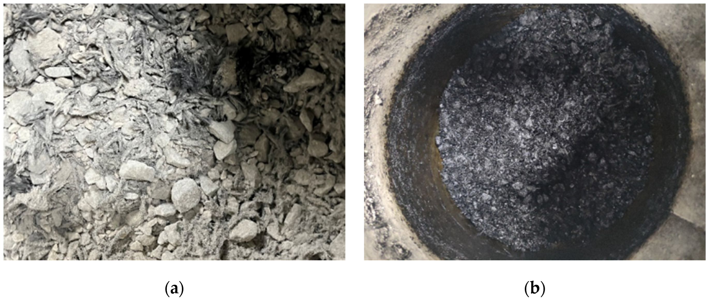
From Figure 6, it was found that the carbon fibers in Process I were heavily agglomerated. The carbon fibers are more homogeneous in Process II, which is beneficial to the formation of a conductive network in carbon fiber–carbon fiber powder conductive asphalt concrete.
From Table 8, it can be seen that the overall resistivity and variability of the Marshall specimens molded by Process II were better than Process I. It was further demonstrated that Process II facilitates the homogeneity of carbon fiber dispersion. Process II will be adopted in a subsequent study.
3.2.2. Grading Selection
In this study, AC grading was used for asphalt concrete mix design. AC-13 grading and AC-16 grading (Table 9) were selected initially, combined with the requirements for the use of the upper surface layer of the pavement.
The Marshall specimens of AC-13 grading and AC-16 grading were molded, while the carbon fiber content was 0.4%, the carbon fiber powder content was 2.0%, and the oil–stone ratio was 5.0%. Resistivity is used as a measure of which grading is more suitable for conductive asphalt concrete and more beneficial for carbon fibers to build three-dimensional conductive networks. Specific data are shown in Table 10.
It can be found that the resistivity of AC-16 is 44% lower than AC-13, which is more beneficial for carbon fibers to build three-dimensional conductive networks. Therefore, AC-16 grading was used in this study.
3.2.3. Optimal Content of Carbon Fiber
In this paper, the optimal content of the carbon fiber is determined based on the control variate method. And the range of the carbon fiber content was initially determined to be 0.3%~0.7% based on the results of the previous test. The test results are shown in Figure 7.
From Figure 7, it can be seen that the resistivity of conductive asphalt concrete decreases with the increase in the carbon fiber content, and the resistivity changes less with the carbon fiber content when the content reaches 0.4%. The reason for this is that the three-dimensional conductive network constructed by carbon fibers in conductive asphalt concrete is basically completed at this time. The optimal content of carbon fiber was finally determined to be 0.4%, combined with the microscopic dispersion of 0.4% carbon fiber in asphalt concrete (Figure 8).
3.2.4. Optimal Content of Carbon Fiber Powder
Due to carbon fiber powder adversely affecting the adhesion of the asphalt mastic, especially in water–temperature coupling conditions, this will make its adhesion further reduced and will affect the water stability of conductive asphalt concrete. Therefore, the water stability and electrical conductivity of conductive asphalt concrete need to be considered together while determining the optimum content of carbon fiber powder. In this study, the freeze–thaw splitting strength ratio, residual stability, and resistivity are used as evaluation indexes to determine the optimal content of carbon fiber powder; the test results are shown in Figure 9.
In Figure 9, with the increase in the carbon fiber powder content, the residual stability and freeze–thaw splitting strength ratio decreases, and the resistivity decreases and then increases. However, the freeze–thaw splitting strength ratio does not meet the requirements when the content of carbon fiber powder reaches 2.5% according to the Specifications for the Design of High–Asphalt Pavement. And a large number of agglomeration phenomenon will occur when the carbon fiber powder is doped too much, which is not beneficial to the formation of a conductive pathway.
The basic properties of the asphalt mastic with 2.0% carbon fiber powder were tested to measure the effect of adding carbon fiber powder on asphalt mastic properties. The test results are shown in Table 11.
From Table 11, the three major indexes of asphalt mastic with 2.0% carbon fiber powder are close to the matrix asphalt. It is shown that the addition of 2% carbon fiber powder has less effect on the properties of asphalt.
3.2.5. Optimal Oil–Stone Ratio
The optimal oil–stone ratio was determined by the performance test of conductive asphalt concrete specimens molded in accordance with the specifications. Based on the experience of previous tests, 4.0%, 4.5%, 5.0%, 5.5%, and 6.0% were selected as the test oil–stone ratios. And four specimens were molded for each group of tests. The Marshall stability, flow value, gross bulk density, and maximum relative density of each Marshall specimen were tested, respectively, and the theoretical maximum density, air voids (VVs), asphalt saturation (VFA), and voids in the mineral aggregate (VMA) of each specimen were calculated. The test results are shown in Table 12.
It was found that there is a slight variation in resistivity when the oil–stone ratio is in the range of 4.5%–6.0%. Therefore, the optimal oil–stone ratio should be determined by combining with the Marshall mix design. The relationship between the gross bulk density, air voids (VVs), asphalt saturation (VFA), voids in mineral aggregate (VMA), Marshall stability, flow value, and oil–stone ratio is shown in Figure 10.
From Figure 10, it can be seen that oil–stone ratios of 4.6%, 4.5%, 4.8%, and 5.1%, respectively, correspond to the maximum gross bulk density, the maximum Marshall stability, the median air voids (VVs), and the median asphalt saturation (VFA), then
The range of the oil–stone ratio that satisfies all the performance indicators at the same time is 4.6%–5.5%, then
Thus, the calculation shows that
The optimal oil–stone ratio was determined to be 4.9% based on the Marshall specimen performance test. The basic performance parameters of the carbon fiber–carbon fiber powder conductive asphalt concrete molded with an oil–stone ratio of 4.9% are shown in Table 13.
The resistivity of carbon fiber–carbon fiber powder conductive asphalt concrete with a 4.9% oil–stone ratio is 0.98 . The electrical conductivity was better than that of the previous tests, and the 4.9% oil–stone ratio was used in all the subsequent tests.
3.3. The Study of Electrothermal Performance
3.3.1. Temperature Rise Test of Marshall Specimens
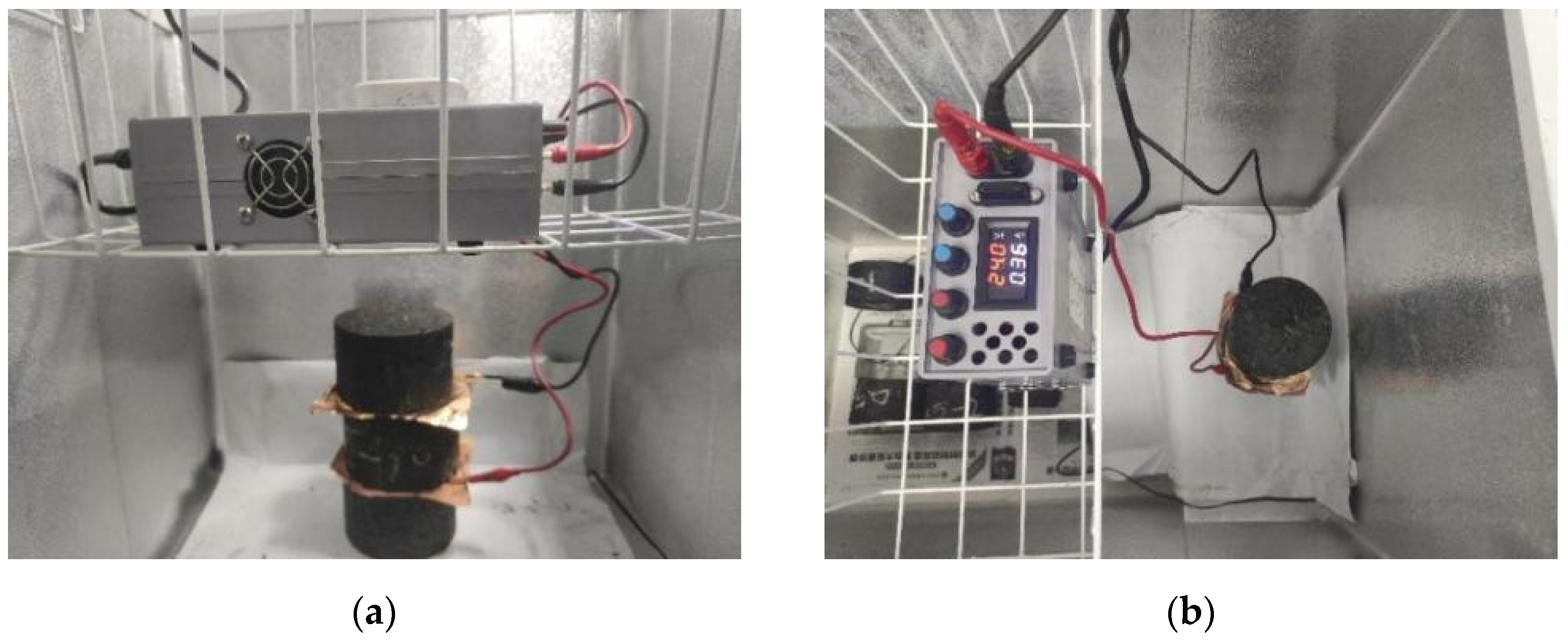
To assure that the internal and external temperatures of the Marshall specimens were consistent, the Marshall specimens were placed in a refrigerator at a temperature of 0 °C for 16 h. Copper electrodes were attached to the upper and lower ends of the specimen while connecting the transformer. The 36v DC voltage was selected to ensure the safety of the energization. The test is shown in Figure 11. The UNI-TREND Uti120S infrared thermal imager was used to test the temperature of the specimens. And the temperature was tested and recorded in one-minute intervals after the power was switched on. The whole process was carried out in a refrigerator at a temperature of 0 °C to simulate the real situation. The temperature variation with time is shown in Figure 12.
The temperature of the Marshall specimens shows a nonlinear increase with the time of the energization. The reason for this is that when the temperature difference between the Marshall specimen and the test environment becomes larger, the rate of heat loss becomes faster, resulting in a slower rise in the specimen’s temperature per unit of time. The voltage was kept constant throughout the test, and the current did not vary, reflecting the stabilization of the energy transformation in conductive asphalt concrete Marshall specimens. The heat transformation rate was calculated according to the relevant parameters of the existing relevant research results [11,30,31]. As shown in Table 14, the conductive asphalt concrete Marshall specimens have a high heat transformation rate of 83.09%.
3.3.2. Temperature Rise Test of Rutting Slab
Firstly, a 300 mm × 300 mm × 50 mm carbon fiber–carbon fiber powder conductive asphalt concrete rutting slab was prepared. Then, the surface of the rutting slab was divided into five points, A, B, C, D, and E, and copper electrodes were attached on both sides of the rutting slab (as shown in Figure 13). To assure that the internal and external temperatures of the rutting slabs were consistent, the rutting slabs were placed in a refrigerator at a temperature of 0 °C for 16 h. The temperatures of the five points were tested at 10 min intervals after being connected to a 36V DC voltage. The temperature variation with time is shown in Figure 14.
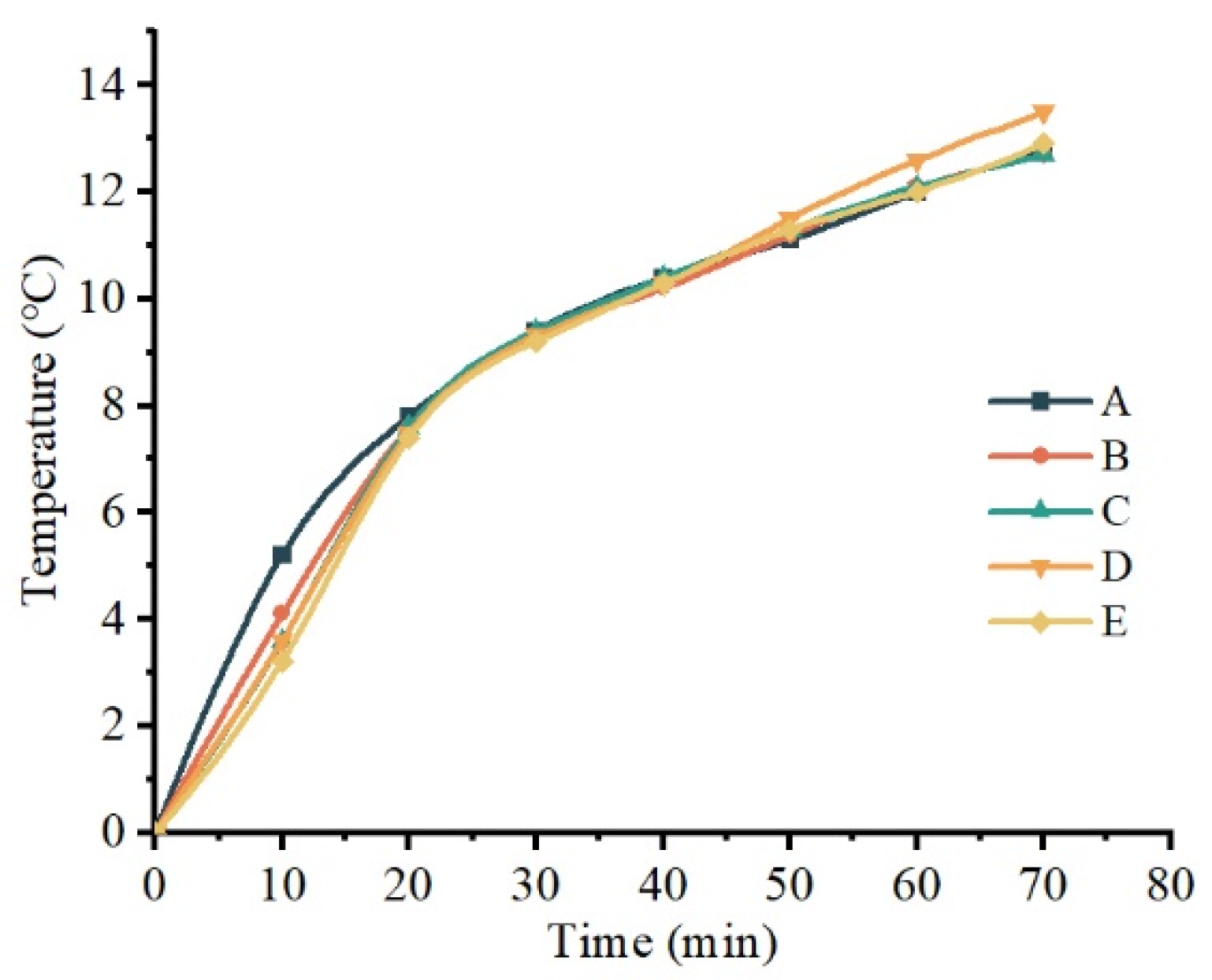
As can be seen from Figure 14, the surface temperature of the rutting slab rises slowly after 30 min of heating, and the whole warming process shows a nonlinear variation. The reason for this is that when the temperature difference between the rutting slab with a large surface area and the test environment becomes larger, the rate of heat loss becomes faster. The heat transformation rate of the rutting slab was calculated and is shown in Table 15.
As can be seen from Table 15, the heat transformation rate of the rutting slab is 78.55%, which is slightly lower than that of the Marshall specimens. The reason for this is that rutting slabs experience more heat loss due to a larger surface area being in contact with the environment than Marshall specimens.
4. Conclusions
In this paper, AFM and MDs were used to study the carbon fiber powder mechanism of action, guide the preparation of conductive asphalt concrete, and study the electrothermal properties of conductive asphalt concrete. The key findings of this research can be summarized as follows:
(1) The adhesion of the asphalt mastic will be affected by carbon fiber powder, meaning that the weakening impact will be further strengthened under water–temperature coupling conditions.
(2) The optimum contents of carbon fiber and carbon fiber powder were determined as 0.4% and 2.0%. And the optimal oil–stone ratio was determined to be 4.9%; therefore, Process II and AC-16 were selected. Conductive asphalt concrete with a resistivity of 0.98 was ultimately prepared.
(3) The study of electrothermal performance shows that the heat transformation rate of the Marshall specimens and rutting slab is 83.09% and 78.55%. Snow and ice can be removed from the road surface in a remarkably short period of time, ensuring that the road is safe and traffic-free.
Author Contributions
Conceptualization, X.L.; methodology, X.L. and H.Z.; data curation, Z.Z. and H.Z.; writing—original draft preparation, Z.Z. and H.Z.; writing—review and editing, X.L.; visualization, Z.Z. and H.M.; project administration, F.S.; funding acquisition, X.L. and F.S. All authors have read and agreed to the published version of the manuscript.
Funding
This research received no external funding.
Institutional Review Board Statement
Not applicable.
Informed Consent Statement
Not applicable.
Data Availability Statement
Data are contained within the article.
Conflicts of Interest
Author Fangzhi Shi was employed by the company Road Engineering Technology Research Institute Co., Ltd. The remaining authors declare that the research was conducted in the absence of any commercial or financial relationships that could be construed as a potential conflict of interest.
References
- Fang, Y.; Li, Z.Y.; Yue, Z.P.; Guo, Z.Y. Dynamic Speed Limit and Warning Program on Horizontal Curve Section of Mountain Highway. Highw. Eng. 2012, 37, 19. [Google Scholar]
- Wan, Y.J. Research on The Freeway Traffic Accidents and Countermeasures under Snow and Ice Conditions. Master’s Thesis, Southeast University, Nanjing, China, 2015. [Google Scholar]
- Team, E. Review on China’s Pavement Engineering Research·2020. China J. Highw. Transp. 2020, 33, 1–66. [Google Scholar]
- Huang, W.R.; Yang, Y.Z.; Song, P. Study on Properties of Graphene-carbon Fiber Conductive Asphalt Concrete. Highw. Eng. 2021, 46, 144–149. [Google Scholar]
- Chung, D.D.L. Electrical conduction behavior of cement-matrix composites. J. Mater. Eng. Perform. 2002, 11, 194–204. [Google Scholar] [CrossRef]
- Ding, Q.J.; Wu, X.W.; Liu, X.Q.; Shen, F.; Hu, S.G. Electrical Performance of Conductive SMA Containing Graphite. J. Build. Mater. 2009, 12, 121–126. [Google Scholar]
- Qin, F. Study on corrosion performance of manganese slag asphalt mixture. New Build. Mater. 2012, 39, 43–46,56. [Google Scholar]
- Wu, S.P.; Mo, L.T.; Shui, Z.H.; Xuan, D.X.; Yang, W.F.; Xue, Y.J. Preparation of Electrically Conductive Asphalt. J. Wuhan Univ. Technol. (Transp. Sci. Eng.) 2002, 26, 567–570. [Google Scholar]
- Shu, M.Y.; Song, G.Q.; Chen, Y.G. The research on electrothermal and mechanical properties of conductive asphalt concrete. New Build. Mater. 2011, 4, 9–12. [Google Scholar]
- Yang, X.W. Properties of Steel Fiber Asphalt Concrete and Its Application. J. Chongqing Jianzhu Univ. 2008, 30, 136–140. [Google Scholar]
- Yang, Z.H. Research on Preparation and Performance of Conductive Graphite Carbon Fiber Asphalt Concrete. Master’s Thesis, Changsha University of Science & Technology, Changsha, China, 2015. [Google Scholar]
- Song, P. Study on Preparation and Properties of Graphene Conductive Asphalt Concrete. Master’s Thesis, Chongqing Jiaotong University, Chongqing, China, 2019. [Google Scholar]
- Liu, K. Preparation Technology and Electro-Thermal Characteristics of Carbon Fiber/Graphene Conductive Asphalt Concrete. Master’s Thesis, Harbin Institute of Technology, Harbin, China, 2018. [Google Scholar]
- Hu, T.W.; Huo, H.F.; Zhang, P.H.; Wang, J.B.; Huang, G.T. Conductive Characteristic Research of Carbon Fiber Asphalt Concrete. New Build. Mater. 2017, 44, 58–61, 80. [Google Scholar]
- Zha, X.D.; Cai, L.; Cao, Y.X. Performance Experiments of Carbon Fiber-reinforced Conductive SBS Modified Asphalt Mixture. J. Chang. Univ. Sci. Technol. (Nat. Sci.) 2014, 1, 10–15, 23. [Google Scholar]
- Zhang, Y.; Liu, X.F.; Yan, S.T.; Li, X. Study on mechanical properties of glass fiber composites based on carbon fiber powder modified epoxy resin. J. Funct. Mater. 2020, 51, 11103–11109. [Google Scholar]
- Jin, T.Y.; Tian, X.S.; Cui, J.; Lu, Y.; Kong, L.J. Mechanical and Electrical Properties of Carbon Fiber Powder-Steel Slag Cement Based Composites. Bull. Chin. Ceram. Soc. 2015, 34, 3601–3605. [Google Scholar]
- Shan, L.Y.; Zhang, E.H.; Liu, S.; Xu, H.L.; Tan, Y.Q. Analysis of Microscopic Damage Mechanism of Asphalt Binder through Atomic Force Microscopy (AFM). China J. Highw. Transp. 2020, 33, 171–177. [Google Scholar]
- Gao, R.; Zhao, L. Using Atomic Force Microscopy to Evaluate the Moisture Stabitlity of Warm Rubber Modified Asphalt. Bull. Chin. Ceram. Soc. 2018, 37, 4045–4049+4055. [Google Scholar]
- Gao, Y.M.; Zhang, Y.Q.; Yang, Y.; Zhang, J.H.; Gu, F. Molecular dynamics investigation of interfacial adhesion between oxidised bitumen and mineral surfaces. Appl. Surf. Sci. 2019, 479, 449–462. [Google Scholar] [CrossRef]
- Xu, J.Y.; Ma, B.; Mao, W.J.; Si, W.; Wang, X.Q. Review of Interfacial Adhesion Between Asphalt and Aggregate Based on Molecular Dynamics. Constr. Build. Mater. 2023, 362, 129642. [Google Scholar] [CrossRef]
- Wang, Y.Y.; Tan, Y.Q.; Liu, K.; Xu, H.N. Preparation and Electrical Properties of Conductive Asphalt Concretes Containing Graphene and Carbon Fibers. Constr. Build. Mater. 2022, 318, 125875. [Google Scholar] [CrossRef]
- Pei, Z.S. Analysis of Surface Microoscopic Characteristics and Influenceing Factors of Aged Asphalt Materials Based on the Principle of AFM. Master’s Thesis, Harbin Institute of Technology, Harbin, China, 2016. [Google Scholar]
- JTG E20-2011; Standard Test Methods of Bitumen and Bituminous Mixtures for Highway Engineering. Research Institute of Highway Ministry of Transport: Beijing, China, 2011; 373p.
- Yan, J.F. The Application of Asphalt Four Component Determination in Asphalt Products Development. Pet. Asph. 2017, 31, 48–52. [Google Scholar]
- Li, D.D.; Greenfield, M.L. Chemical compositions of improved model asphalt systems for molecular simulations. Fuel 2014, 115, 347–356. [Google Scholar] [CrossRef]
- Li, X.J.; Ouyang, H.; Zhang, H.; Zhao, L.H. Research on Performance of Modified Foamed Asphalt Based on AFM and Molecular Dynamics. Highway 2023, 68, 253–259. [Google Scholar]
- Guo, S.Y. Overview of the Characteristics of Asphalt Bee Structure in AFM Images under Atomic Force Microscope. Subgrade Eng. 2019, 2, 32–38. [Google Scholar]
- Wang, Z.H.; Xu, Y.F.; Qi, X.D.; Liu, X.Y.; Hong, J.J. Research Progress on Influencing Factors of Emulsion Stability with Molecular Dynamics Simulation. Oilfield Chem. 2021, 38, 360–367. [Google Scholar]
- Cao, Y.X. Experimental Researeh on Performances of Conductive Modified Asphalt Mixture with Carbon Fiber. Master’s Thesis, Changsha University of Science & Technology, Changsha, China, 2013. [Google Scholar]
- TU, H.; Chen, H.; Wu, S.P.; Mo, L.T.; Wang, H. Calculating Method for Heat Output Power Based on Removing Snow and Ice of Conductive Asphalt Concrete. J. Wuhan Univ. Technol. 2009, 31, 37–40. [Google Scholar]
Figure 1.
Conductive asphalt concrete two-electrode method.

Figure 2.
Asphalt–water, asphalt–carbon fiber powder, and asphalt–water–carbon fiber powder models: (a) asphalt–water model; (b) asphalt–carbon fiber powder model; (c) asphalt–water–carbon fiber powder model.
Figure 2.
Asphalt–water, asphalt–carbon fiber powder, and asphalt–water–carbon fiber powder models: (a) asphalt–water model; (b) asphalt–carbon fiber powder model; (c) asphalt–water–carbon fiber powder model.

Figure 3.
Morphology of carbon fiber powder asphalt mastic before and after water–temperature coupling: (a) plan of carbon fiber powder asphalt mastic; (b) three-dimensional view of carbon fiber powder asphalt mastic; (c) plan of water–temperature coupled carbon fiber powder asphalt mastic; (d) three-dimensional view of water–temperature coupled carbon fiber powder asphalt mastic.


Figure 4.
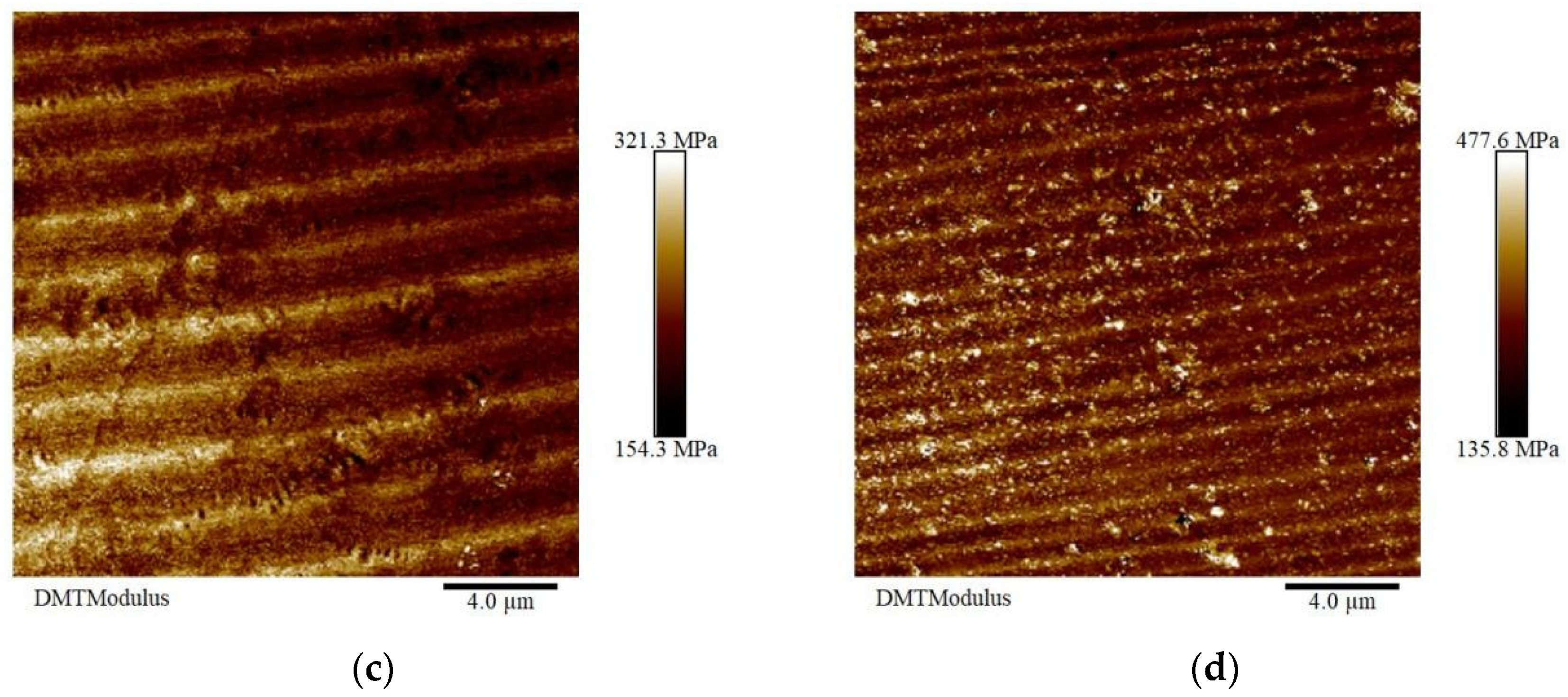
Micromechanics of carbon fiber powder asphalt mastic before and after water–temperature coupling: (a) adhesion of carbon fiber powder asphalt mastic; (b) adhesion of water–temperature coupled carbon fiber powder asphalt mastic; (c) DMT modulus of carbon fiber powder asphalt mastic; (d) DMT modulus of water–temperature coupled carbon fiber powder asphalt mastic.
Figure 4.
Micromechanics of carbon fiber powder asphalt mastic before and after water–temperature coupling: (a) adhesion of carbon fiber powder asphalt mastic; (b) adhesion of water–temperature coupled carbon fiber powder asphalt mastic; (c) DMT modulus of carbon fiber powder asphalt mastic; (d) DMT modulus of water–temperature coupled carbon fiber powder asphalt mastic.


Figure 5.
Two mixing processes for carbon fiber–carbon fiber powder conductive asphalt concrete: (a) Process I; (b) Process II.
Figure 5.
Two mixing processes for carbon fiber–carbon fiber powder conductive asphalt concrete: (a) Process I; (b) Process II.

Figure 6.
The mixing homogeneity of the two mixing processes: (a) Process I; (b) Process II.

Figure 7.
Relation between resistivity and carbon fiber content.

Figure 8.
Microscopic distribution of 0.4% carbon fibers.

Figure 9.
Relationship curve between carbon fiber powder content and evaluation indexes.

Figure 10.
(a) Relationship between gross bulk density and oil–stone ratio; (b) relationship between air voids (VVs) and oil–stone ratio; (c) relationship between voids in mineral aggregate (VMA) and oil–stone ratio; (d) relationship between asphalt saturation (VFA) and oil–stone ratio; (e) relationship between Marshall stability and oil–stone ratio; (f) relationship between flow value and oil–stone ratio.

Figure 11.
Temperature rise test of Marshall specimens: (a,b).

Figure 12.
Temperature variation in Marshall specimens with time.

Figure 13.
Temperature rise test of rutting slabs.

Figure 14.
Temperature variation in rutting slab with time.


Table 1.
Basic properties of asphalt.
| Item | Test Value | Test Method | Specification |
|---|---|---|---|
| Penetration at 25 °C/(0.1 mm) | 69.5 | T0604 | 60∼80 |
| Softening point/°C | 46.3 | T0606 | ≥43 |
| Ductility at 15 °C/mm | 134.4 | T0605 | ≥100 |
| Dynamic viscosity at 60 °C/(Pa·s) | 456.0 | T0620 | ≥160 |
| Density at 15 °C/(g/cm3) | 1.02 | T0603 | Test |
Table 2.
Coarse aggregate specifications.
| Test Item | Unit | Standard Requirement | Coarse Aggregate Test Result | Assess | Testing Method | ||
|---|---|---|---|---|---|---|---|
| 10~16 mm | 5~10 mm | 3~5 mm | |||||
| Apparent Density | g/cm3 | — | 2.742 | 2.732 | 2.726 | Measured | T0304 |
| Apparent Relative Density | g/cm3 | ≥2.60 | 2.751 | 2.740 | 2.734 | Qualified | T0304 |
| Bulk Relative Density | g/cm3 | Measured | 2.713 | 2.719 | 2.710 | Qualified | T0304 |
| Water Absorption Rate | % | ≤2.0 | 0.5 | 0.4 | 0.3 | Qualified | T0304 |
| Adhesion to Asphalt | Stage | ≥5 | 5 | — | — | Qualified | T0616 |
| Sturdiness | % | ≤12 | 7 | Qualified | T0314 | ||
| Water Washing Method <0.075 mm Granule Content | % | ≤1 | 0.1 | 0.3 | 0.4 | Qualified | T0310 |
Table 3.
Fine aggregate specifications.
| Test Item | Unit | Standard Requirement | Test Result | Assess | Testing Method |
|---|---|---|---|---|---|
| Apparent Density | g/cm3 | Measured | 2.701 | Qualified | T0328 |
| Apparent Relative Density | — | ≥2.50 | 2.705 | — | T0328 |
| Robustness (>0.3 mm) | % | ≤12 | 9 | Qualified | T0340 |
| Sand Equivalent | % | ≥60 | 65 | Qualified | T0334 |
Table 4.
Basic parameters of carbon fiber and carbon fiber powder.
| Categories | Tensile Strength | Density | Resistivity | Fiber Diameter | Carbon Content | Fineness |
|---|---|---|---|---|---|---|
| CF | 4900 MPa | 1.75 g/cm3 | 1.5 × 10⁻³ | 7 µm | 97% | / |
| CFP | 4900 MPa | 1.75 g/cm3 | 1.5 × 10⁻³ | 7 µm | 97% | 1200 mesh |
Table 5.
Calculation and test results of the planning solution method.
| Categories | No. | Molecular Formula | Number of Molecules | Calculate Four-Component Ratio | Actual Four-Component Ratio |
|---|---|---|---|---|---|
| Saturate | A | C30H62 | 16 | 5.793% | 5.534% |
| B | C35H62 | 8 | |||
| Aromatic | A | C35H44 | 72 | 42.055% | 42.176% |
| B | C30H46 | 80 | |||
| Resin | A | C36H57N | 16 | 21.249% | 21.836% |
| B | C40H59N | 8 | |||
| C | C29H50O | 8 | |||
| D | C18H10S2 | 64 | |||
| E | C40H60S | 8 | |||
| Asphaltene | A | C42H54O | 32 | 30.902% | 30.454% |
| B | C66H81N | 24 | |||
| C | C51H62S | 24 |
Table 6.
Total energy of dynamic relaxation for molecular modeling.
| Categories | Asphalt | CFP | H2O | Asphalt–H2O | Asphalt–CFP | Asphalt–H2O–CFP |
|---|---|---|---|---|---|---|
| 86,573.935 | 837,933.686 | −6831.201 | 85,578.532 | 1,087,144.564 | 1,283,874.079 |
Table 7.
Asphalt–carbon fiber powder and asphalt–water–carbon fiber powder interfacial binding energy.
Table 7.
Asphalt–carbon fiber powder and asphalt–water–carbon fiber powder interfacial binding energy.
| Categories | |||||
|---|---|---|---|---|---|
| Asphalt–CFP | 86,573.935 | 837,933.686 | 1,087,144.564 | 162,636.943 | −162,636.943 |
| Asphalt–H2O–CFP | 85,578.532 | 837,933.686 | 1,283,874.079 | 360,361.861 | −360,361.861 |
Table 8.
The resistivity of specimens obtained by the two mixing processes.
| Mixing Process | Number | Resistivity (Ω·m) | Average Resistivity (Ω·m) | Coefficient of Variation |
|---|---|---|---|---|
| Process I | 1 | 2.72 | 2.75 | 0.168 |
| 2 | 2.17 | |||
| 3 | 2.77 | |||
| 4 | 3.33 | |||
| Process II | 1 | 2.39 | 2.68 | 0.083 |
| 2 | 2.95 | |||
| 3 | 2.99 | |||
| 4 | 2.40 |
Table 9.
Grading design of AC-13 and AC-16.
| Mixture Type | Sieve Size/mm | 19.0 | 16.0 | 13.2 | 9.5 | 4.75 | 2.36 | 1.18 | 0.6 | 0.3 | 0.15 | 0.075 |
|---|---|---|---|---|---|---|---|---|---|---|---|---|
| AC-16 | Passing Rate/% | 100.0 | 99.0 | 90.6 | 65.1 | 38.3 | 27.8 | 22.6 | 17.6 | 10.5 | 5.2 | 2.9 |
| AC-13 | Passing Rate/% | 100.0 | 99.7 | 96.8 | 82.8 | 56.2 | 31.4 | 24.0 | 16.4 | 10.0 | 6.0 | 4.0 |
Table 10.
Conductivity test data of AC-13 and AC-16.
| Grading | Number | Carbon Fiber Content (%) | Carbon Fiber Powder Content (%) | Resistance (Ω) | Resistivity (Ω·m) | Average Resistivity (Ω·m) |
|---|---|---|---|---|---|---|
| AC-13 | 1 | 0.4% | 2.0% | 15.4 | 2.39 | 2.68 |
| 2 | 18.1 | 2.95 | ||||
| 3 | 17.7 | 2.99 | ||||
| 4 | 15.5 | 2.40 | ||||
| AC-16 | 1 | 0.4% | 2.0% | 11.8 | 1.52 | 1.49 |
| 2 | 10.7 | 1.37 | ||||
| 3 | 12.6 | 1.60 | ||||
| 4 | 11.4 | 1.46 |
Table 11.
Properties of asphalt mastic with 2% carbon fiber powder.
| Testing Program | Unit | Test Results | Evaluate | Test Methods |
|---|---|---|---|---|
| Penetration (25 °C, 5 s, 100 g) | 0.1 mm | 70.3 | eligible | T0604 |
| Softening Point (R&B) (the ring-and-ball method) | °C | 43.8 | eligible | T0606 |
| Ductility (5 °C, 1 cm/min) | cm | 9.3 | eligible | T0605 |
Table 12.
Basic properties for carbon fiber–carbon fiber powder conductive asphalt concrete with different oil–stone ratio.
Table 12.
Basic properties for carbon fiber–carbon fiber powder conductive asphalt concrete with different oil–stone ratio.
| Oil–Stone Ratio | Gross Bulk Density (g/cm3) | Air Voids (VVs) (%) | Asphalt Saturation (VFA) (%) | Voids in Mineral Aggregate (VMA) (%) | Marshall Stability (KN) | Flow Value (mm) | Resistivity (Ω·m) |
|---|---|---|---|---|---|---|---|
| 4.0% | 2.379 | 6.91 | 52.446 | 14.701 | 12.54 | 3.02 | 2.54 |
| 4.5% | 2.400 | 5.043 | 63.763 | 13.917 | 13.76 | 3.54 | 1.44 |
| 5.0% | 2.396 | 4.304 | 69.387 | 14.059 | 11.89 | 4.08 | 1.50 |
| 5.5% | 2.398 | 3.264 | 76.685 | 14.000 | 9.42 | 4.41 | 1.55 |
| 6.0% | 2.399 | 2.342 | 83.217 | 13.956 | 8.84 | 5.10 | 1.35 |
Table 13.
Basic performance parameters of carbon fiber–carbon fiber powder conductive asphalt concrete with 4.9% oil–stone ratio.
Table 13.
Basic performance parameters of carbon fiber–carbon fiber powder conductive asphalt concrete with 4.9% oil–stone ratio.
| Oil–Stone Ratio (%) | Carbon Fiber Content (%) | Carbon Fiber Powder Content (%) | Resistance (Ω) | Resistivity (Ω·m) | Marshall Stability (KN) | Flow Value (mm) | Gross Bulk Density (g/cm3) |
|---|---|---|---|---|---|---|---|
| 4.9 | 0.4 | 2.0 | 7.7 | 0.98 | 12.10 | 3.95 | 2.400 |
Table 14.
The heat transformation rate of Marshall specimens.
| Resistance Ω | Power Input (ω) | Total Heat (kJ) | Specific Heat Capacity (J/(kg·K)) | Intensify (°C) | Heat Storage (kJ) | Heat Transformation Rate (%) |
|---|---|---|---|---|---|---|
| 4.93 | 262.88 | 47.32 | 948.66 | 33.7 | 39.32 | 83.09 |
Table 15.
The heat transformation rate of rutting slab.
| Resistance Ω | Power Input (ω) | Total Heat (kJ) | Specific Heat Capacity (J/(kg·K)) | Intensify (°C) | Heat Storage (kJ) | Heat Transformation Rate (%) |
|---|---|---|---|---|---|---|
| 32.1 | 40.37 | 169.56 | 948.66 | 13 | 133.19 | 78.55 |
Disclaimer/Publisher’s Note: The statements, opinions and data contained in all publications are solely those of the individual author(s) and contributor(s) and not of MDPI and/or the editor(s). MDPI and/or the editor(s) disclaim responsibility for any injury to people or property resulting from any ideas, methods, instructions or products referred to in the content. |
© 2024 by the authors. Licensee MDPI, Basel, Switzerland. This article is an open access article distributed under the terms and conditions of the Creative Commons Attribution (CC BY) license (https://creativecommons.org/licenses/by/4.0/).
Share and Cite
MDPI and ACS Style
Li, X.; Zhang, Z.; Zhang, H.; Ma, H.; Shi, F. Preparation of Conductive Asphalt Concrete Based on the Action Mechanism of Conductive Phase Materials. Coatings 2024, 14, 512. https://doi.org/10.3390/coatings14040512
AMA Style
Li X, Zhang Z, Zhang H, Ma H, Shi F. Preparation of Conductive Asphalt Concrete Based on the Action Mechanism of Conductive Phase Materials. Coatings. 2024; 14(4):512. https://doi.org/10.3390/coatings14040512
Chicago/Turabian StyleLi, Xiujun, Zhipeng Zhang, Heng Zhang, Huaiyu Ma, and Fangzhi Shi. 2024. "Preparation of Conductive Asphalt Concrete Based on the Action Mechanism of Conductive Phase Materials" Coatings 14, no. 4: 512. https://doi.org/10.3390/coatings14040512
Note that from the first issue of 2016, this journal uses article numbers instead of page numbers. See further details here.